|
|
|
|
|
|
|
Fast, Easy, Open Technique Development For NDT
Continuing to lead the industry in UT technique development software, Eclipse Scientific's BeamTool 11 offers a robust set of new features and enhancements. Successful inspections start with a plan and BeamTool makes it easy to model, validate and document your Phased Array, TOFD and Conventional Ultrasonic scan plans with confidence.
Easy to use and powerful, BeamTool has continued to evolve and provide tools to improve proficiency and accuracy of ultrasonic inspections. From technicians in the field, to researchers and authors, BeamTool provides the indispensable toolset for the NDT industry.
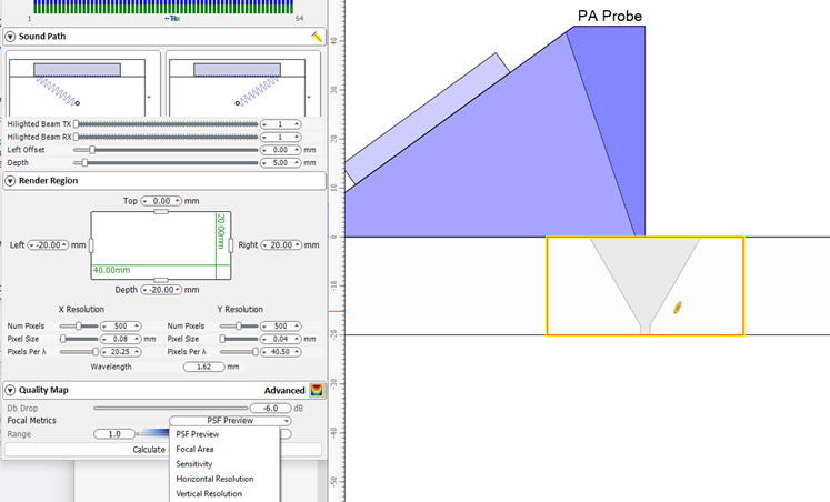
 Focal Quality and Point Spread Function Simulation
Focal Quality and Point Spread Function simulation were introduced in BeamTool10 as a means of assessing the spatial sensitivity and resolution of FMC/TFM techniques. In BeamTool 11 these features have been improved and expanded to support Phased Array beamsets as well. The focal quality simulation allows the user to quickly visualize how the amplitude, shape and size of a point reflector (small side drilled hole) varies throughout the inspection region for a given technique. The user can use this information to select the appropriate essential technique parameters (aperture, focusing, index offset, etc.). Several focal quality metrics derived from the “Point Spread Function (PSF)” can be overlaid on the piece and their precise numerical values read at any given mouse position allowing for direct estimation of target resolution and sizing accuracy.
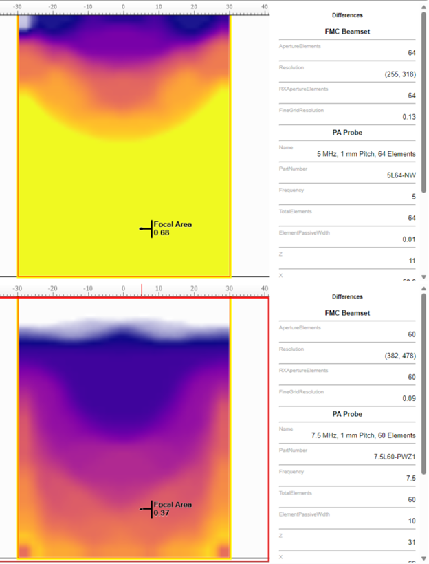
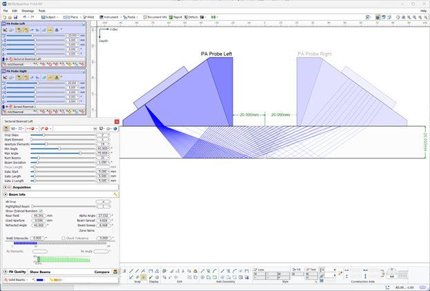
Technique Comparison
New in BeamTool 11 is the ability to quantitatively compare candidate inspection techniques (supported for FMC, Linear, Sectorial and Spread Beamsets). Beamsets generated with different probes (frequency, pitch, wedge parameters), apertures, focusing type (true depth, half path, unfocused) scan type (linear, sectorial, spread/compound) can be selected for comparison and appear in a split-screen view. Focal quality metrics associated with each technique are overlaid on the piece with a consistent palette to facilitate discriminating between them. The point spread function simulation and corresponding focal metrics (sensitivity, focal area, vertical resolution, horizontal resolution, lateral resolution, axial resolution) are displayed independently for each technique for ease of comparison.
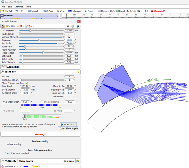
Intelligent Alerts About Inspection Quality Issues (Warnings)
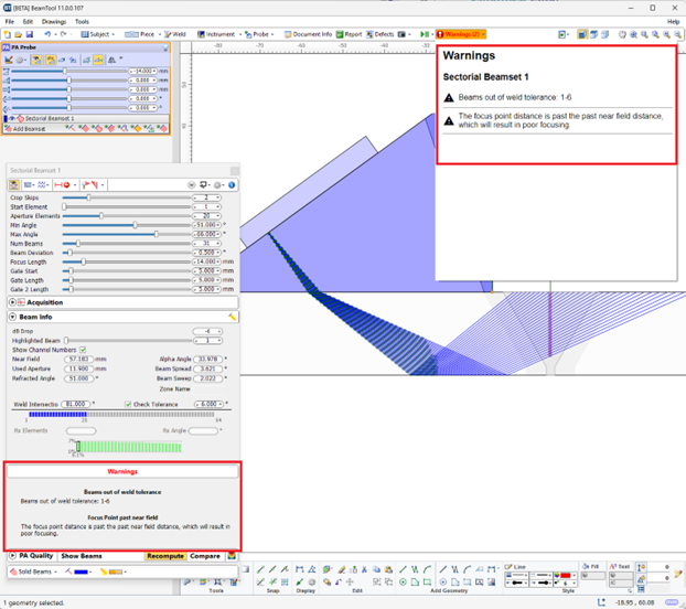
In BeamTool 11 the user is alerted to potential issues with the selected technique by a “Warnings” tab. Technique pitfalls to which the user will be alerted to in the “Warning” tab include:
Warnings for all probes and beamsets can be viewed by selecting the Warnings dropdown in the toolbar and are displayed for the selected beamset under the Warnings heading.
Dynamic Workspace Information
A new “Workspace Information” option has been added in BeamTool 11 which when enabled, provides the user information about the beam nearest to the mouse position – this information includes travel path, time of flight, beam angle, etc.
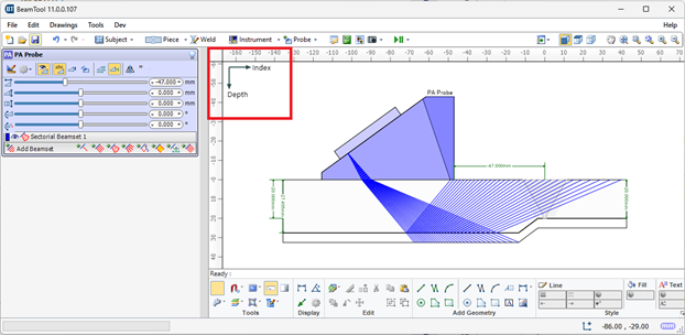
NDT Axes
In response to popular demand, the option to change the coordinate system from the default global Cartesian coordinate system (x,y,z) to the NDT industry standard coordinate system (Index, Depth, Scan) is available in BeamTool 11. When the NDT axes are employed, all pertinent geometric information is labeled with respect to the Index, Depth, Scan axes which may facilitate reporting/technique documentation.
Expanded Support for Simulation/Visualizations in Custom Pieces
In BeamTool 11 the user can now use any of the Point Spread Function/Focal Metric simulation features in custom work pieces (previously only supported in standard pieces). The user may use the CAD tools to represent arbitrary inspection geometries and then select the appropriate component surfaces as the front and back walls of the piece.
Automatic Highlighting/Fading of Active/Inactive Beams & Probes
To facilitate workspace navigation, the probe/beamset closest to the user’s mouse position in the probe/beamset list is automatically highlighted.
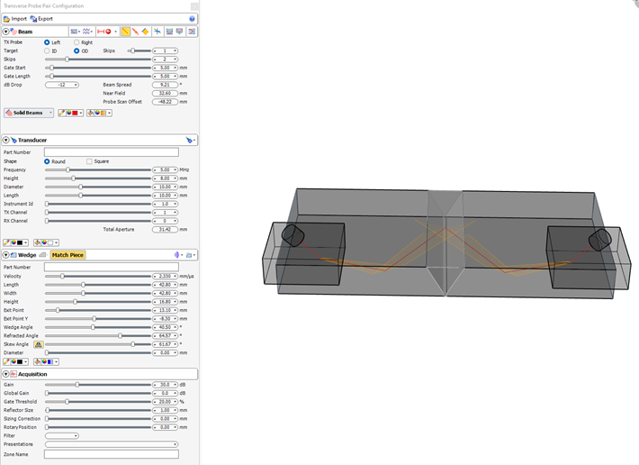
New Probe Type
New Probe Type: Transverse Conventional.
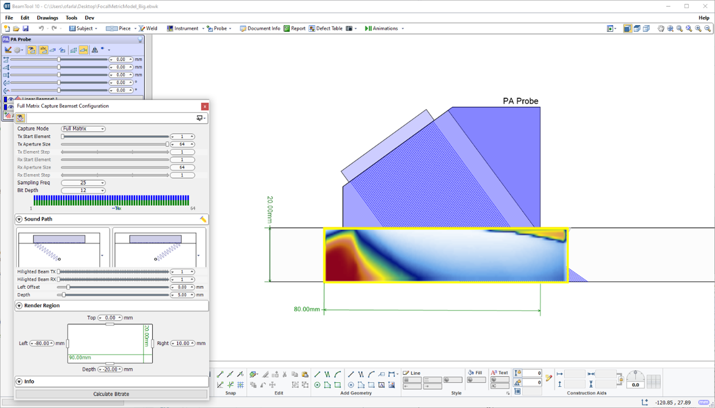
FMC Beamset
New quality metrics including point spread function preview and more parameters.
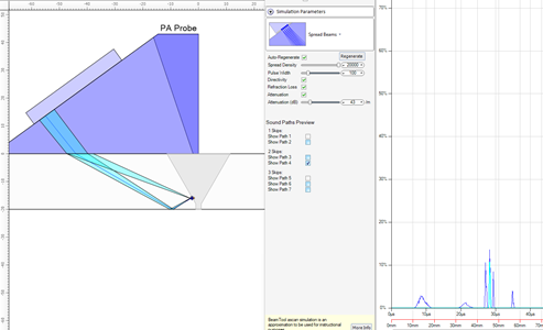
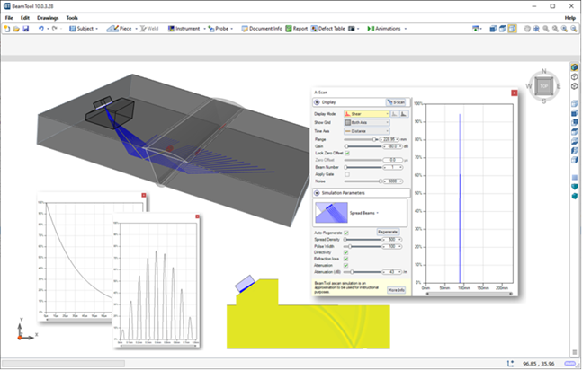
A-Scan Simulator
A-Scan Simulator can now show the travel paths that form the A-scan response.
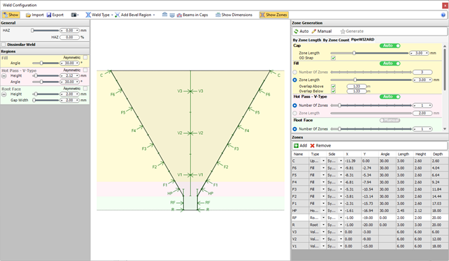
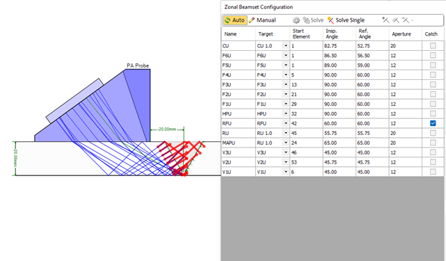
PipeWIZARD Support Changes
New zone configuration interface, ability to solve for Cal block targets instead of Zones, and improved integration between Zonal Cal block and Zonal Beamset.
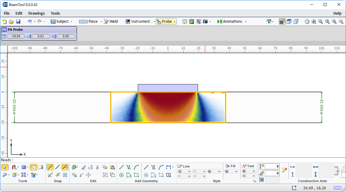
Advanced FMC/TFM Focal Quality Map
Built In Simulation
The Simulation features previously separate from BeamTool are now included when upgrading to or purchasing BeamTool 11! Great as a training aid or for generating training material and conveying principles.
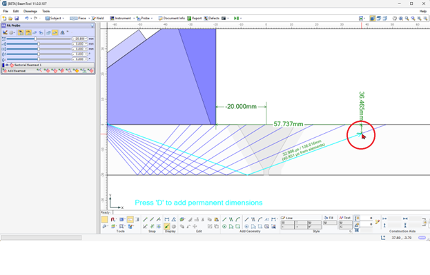
Angle Inspector
Hover over intersecting lines with the Angle Inspector on, and the angle will be displayed overlaid on the workspace.
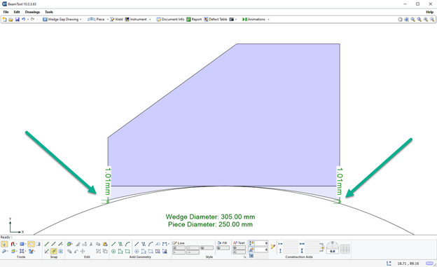
Wedge Gap Drawing
A Wedge Gap drawing can be generated that will show the dimension of any gap between the wedge and the piece due to a mismatch in profiles.

FMC Beamset Validation
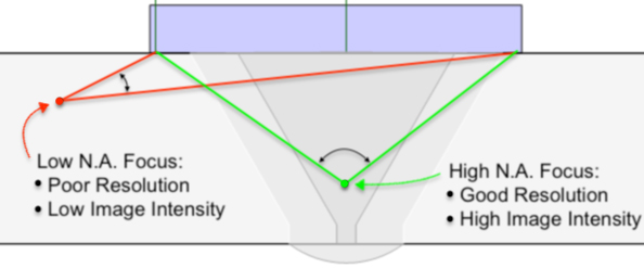
BeamTool can help you choose an appropriate rendering region for an FMC inspections (currently only available for contact FMC inspections) by plotting a Quality Map, which roughly quantifies the resolution and image intensity of reflectors positioned with respect to the probe aperture. This map roughly quantifies the quality of focus for each pixel point in the chosen rendering region by computing the effective "Numerical Aperture", defined as sine of half of the angle between the first and last beams covering the pixel.
The concept of numerical aperture comes from microscopy and represents the angular coverage of a focal point. A low numerical aperture value implies that energy is not effectively focused at a particular point leading to poor resolution and low image intensity, whereas a high numerical aperture value means that energy is highly focused leading to high resolution and high image intensity.
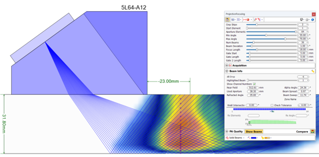
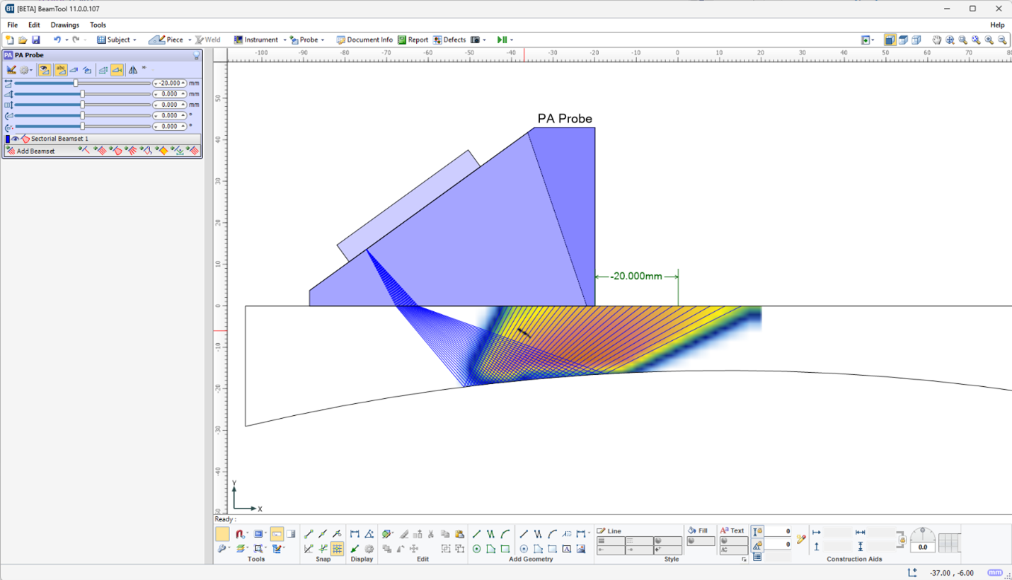
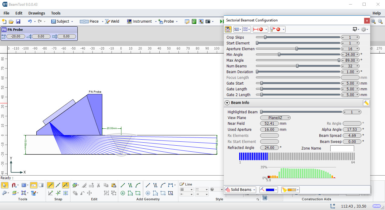
Sectorial Beamset Beam Energy Display
BeamTool now helps you to select the correct range of angles for Phased Array inspections by displaying the energy associated with each beam defined within a beamset. Low energy beams will be difficult to calibrate and require a large amount of gain to be properly normalized. Beams above 50% of the maximum possible transmitted energy are shown as green, between 10% - 50% shown as orange and below 10% are shown as red. The calculated energies take into account the directivity of the probe elements, the transmission coefficient between the wedge and the piece, as well as the reflection coefficients for each skip within the piece.
Spline CAD Support
BeamTool can now import CAD drawings with Splines.
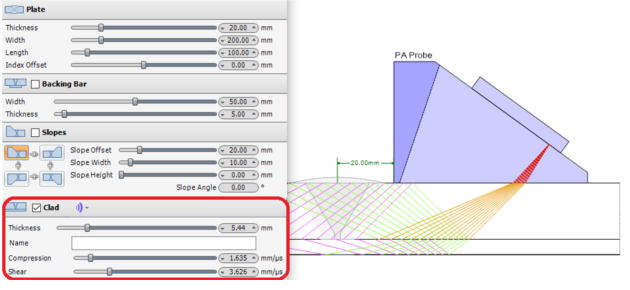
Clad Material Support
A clad layer can now be added to a plate, T, axial or circumferential piece configuration.
Sound Mode Colorization
When both compression and shear paths are displayed, you can now color each sound mode independently.
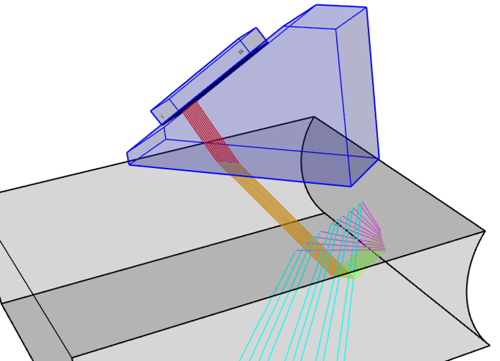
3D Sound Paths Ray-tracer
BeamTool now supports tracing sound paths in 3 dimensions.
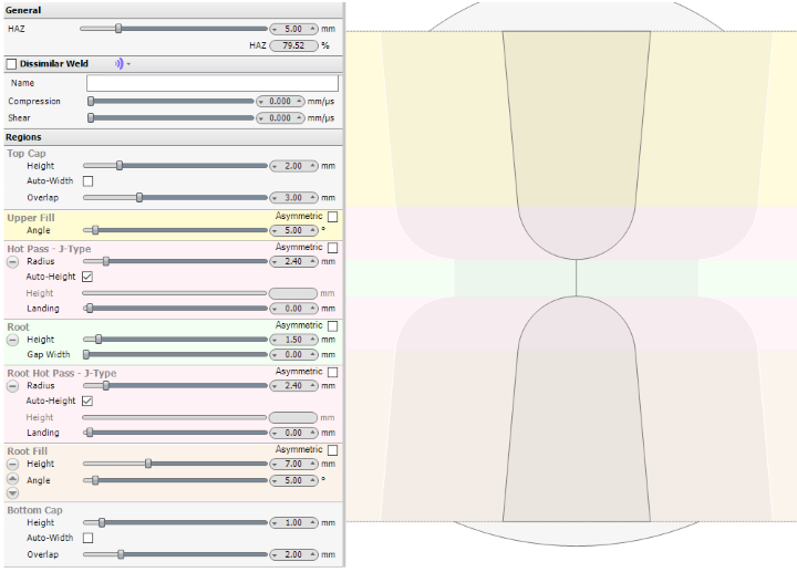
Double J Welds
A J bevel can be created in root to create a double J weld bevel.
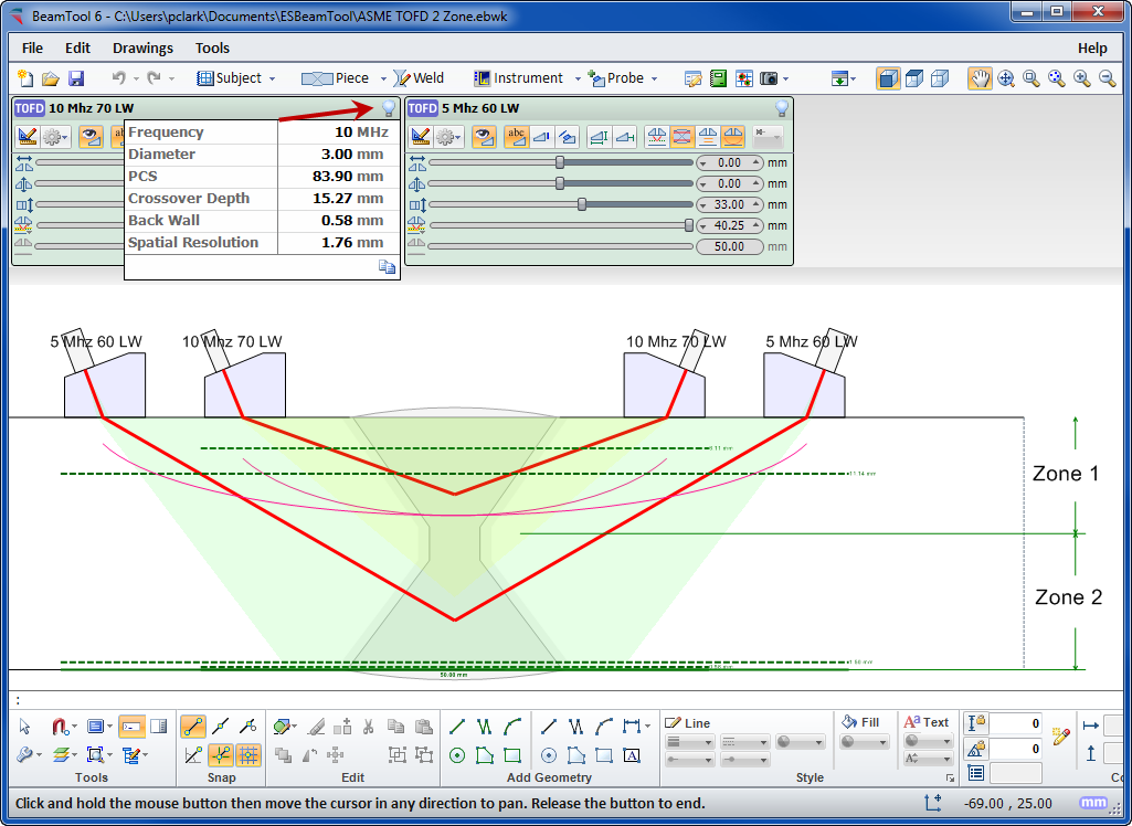
TOFD
Time-Of-Flight Diffraction support provides tools to visualize and confirm zonal coverage. TOFD techniques can be automatically annotated with cross-over dimensions and dead-zone depiction. Effortlessly define Probe Center Separation (PCS) by selecting the cross-over depth you want and BeamTool automatically positions the probes to target your requirements.
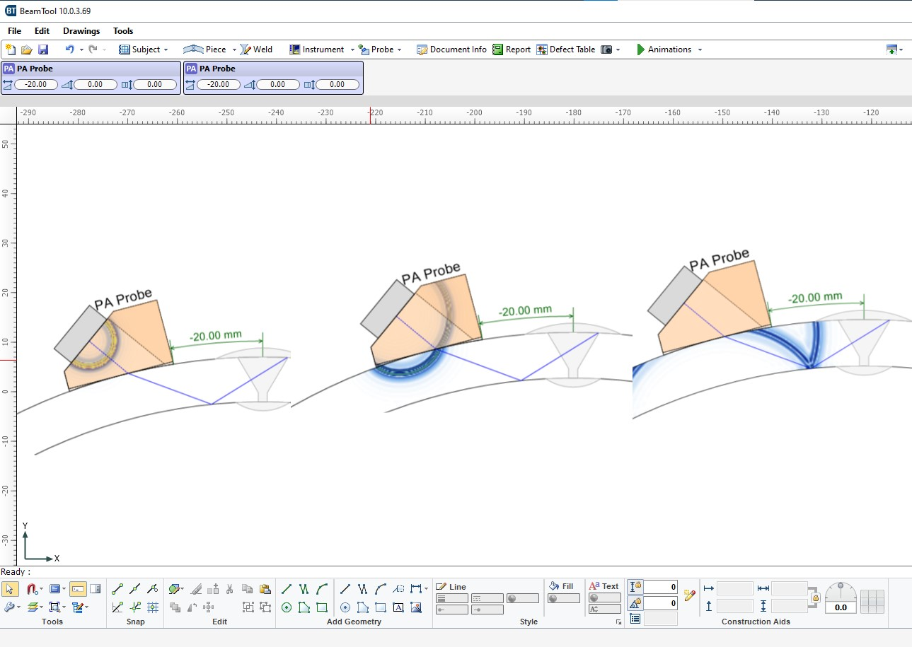
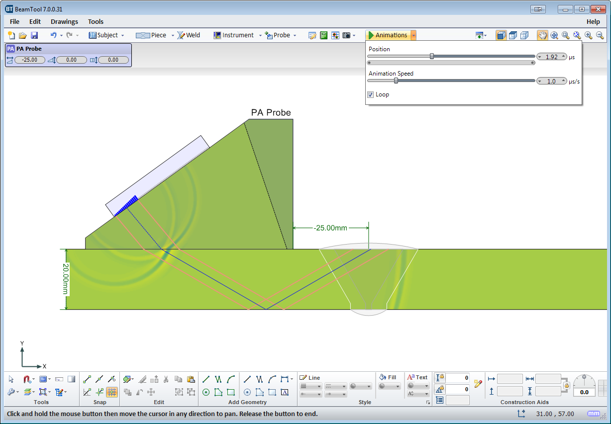
Sound Propagation Animation
Sound Propagation Animation shows how elements firing in a phased array probe constructively form a wave front and how that wave front propagates into the piece.
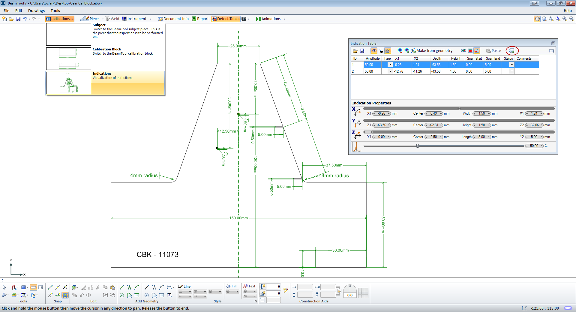
Indication Drawing Set
Indication drawing sets can now be added to the workspace
3D Rendering of Circumferential Piece
Circumferential pieces are now properly represented in 3D View.
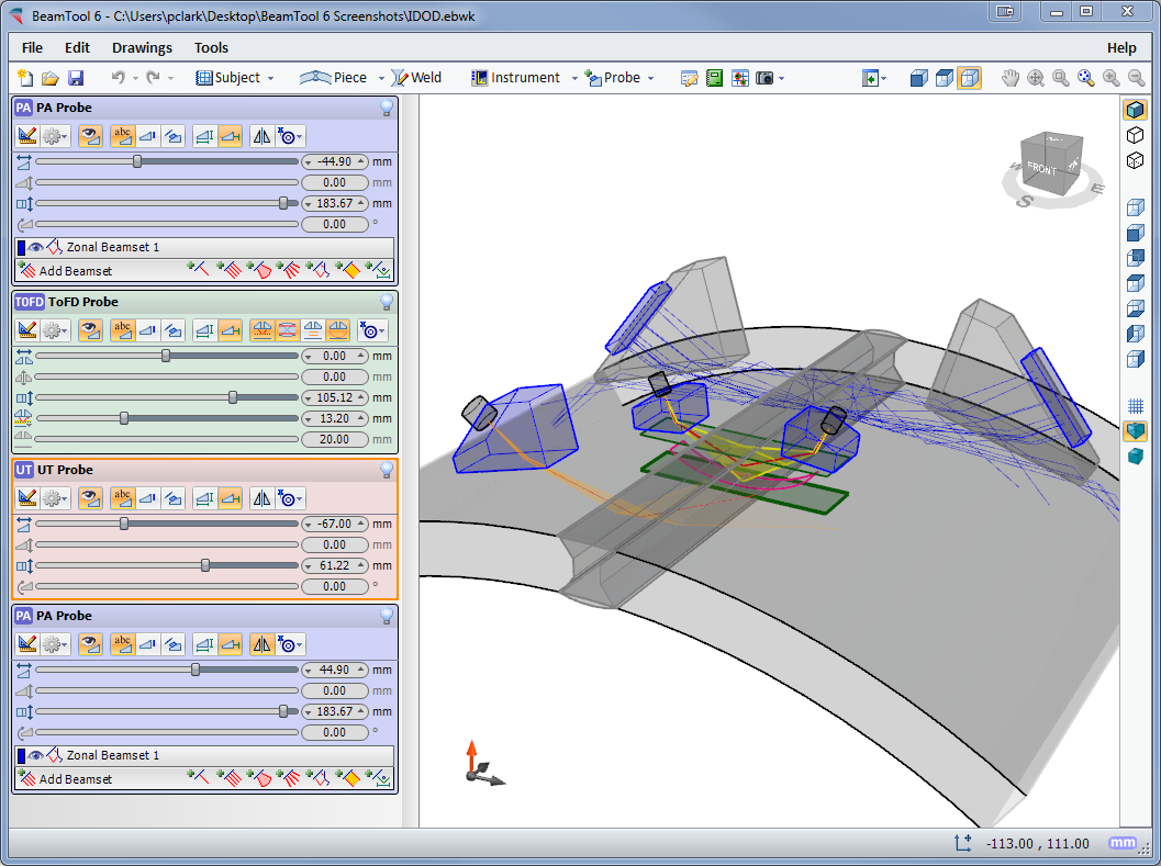
Multi-Discipline Technique Development
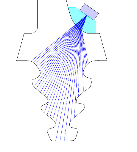
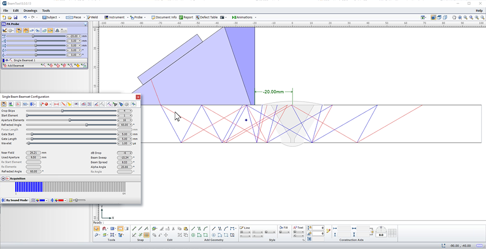
Techniques can be created using multiple probes and multiple disciplines within a single workspace. Combine Phased Array with Conventional UT and TOFD probe configurations to ensure complete coverage. Pitch-catch is a useful technique for viewing unfavourable weld bevels or targeting geometry. Simply select P/C in the phased array configuration and the BeamTool will solve and present the elements required; this feature can be set to reflect off the weld bevel face accounting for return refraction.
BeamTool makes it easy to develop pitch-catch techniques for direct and indirect inspection using a single probe or a pair of probes.
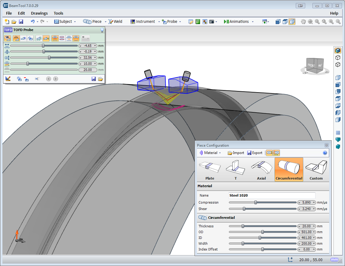
Piece Configuration
BeamTool provides native support for ID/OD type pieces common in pipeline and boilers. The piece editor allows the piece to be easily defined using the OD and ID or thickness of a part. Once the part is configured, phased array and conventional probes can be pinned to the outside or inside of the part. As the user adjusts the probe location, the probe stays pinned to the part and revolves around it.Piece Configuration
BeamTool provides native support for ID/OD type pieces common in pipeline and boilers. The piece editor allows the piece to be easily defined using the OD and ID or thickness of a part. Once the part is configured, phased array and conventional probes can be pinned to the outside or inside of the part. As the user adjusts the probe location, the probe stays pinned to the part and revolves around it.

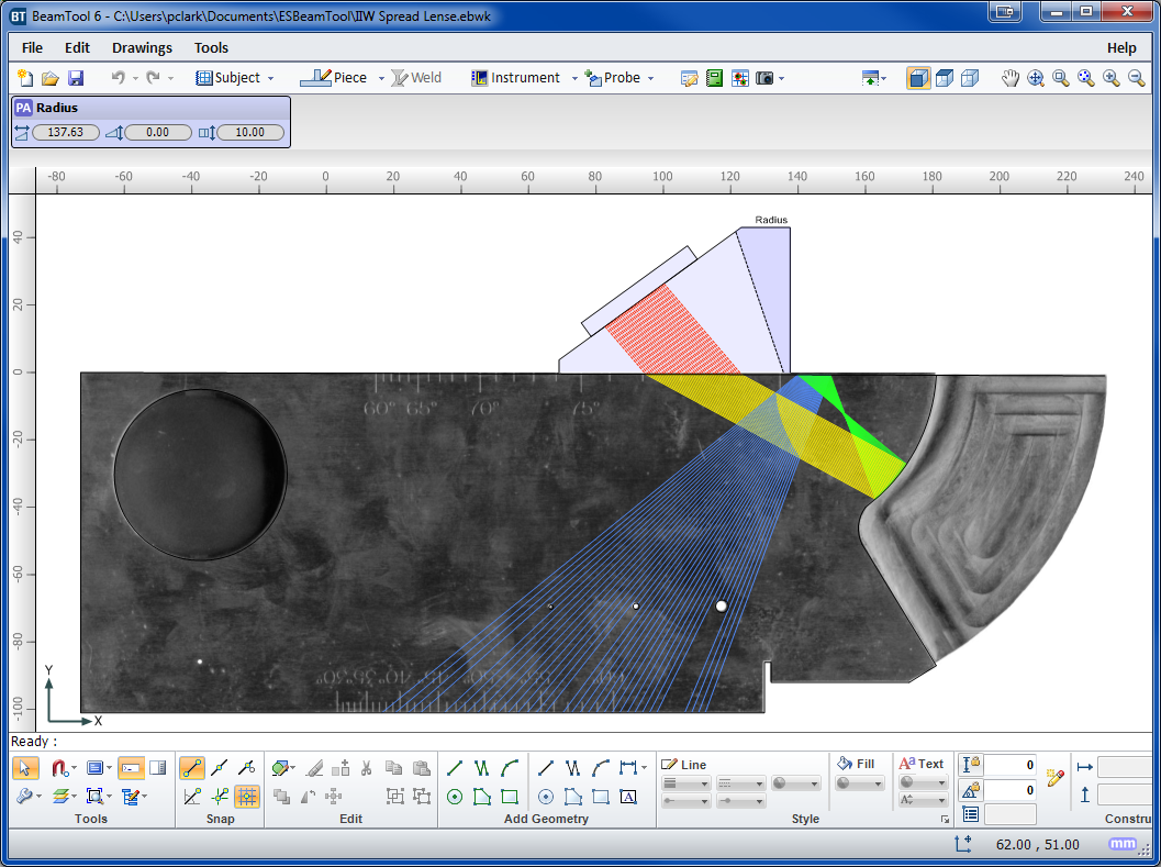
Bitmap Backdrops
Use the bitmap drawing tool to add images to your drawings. Bitmaps can be imported and scaled to be used as a backdrop or to use as a reference to trace over when drawing complex specimens.
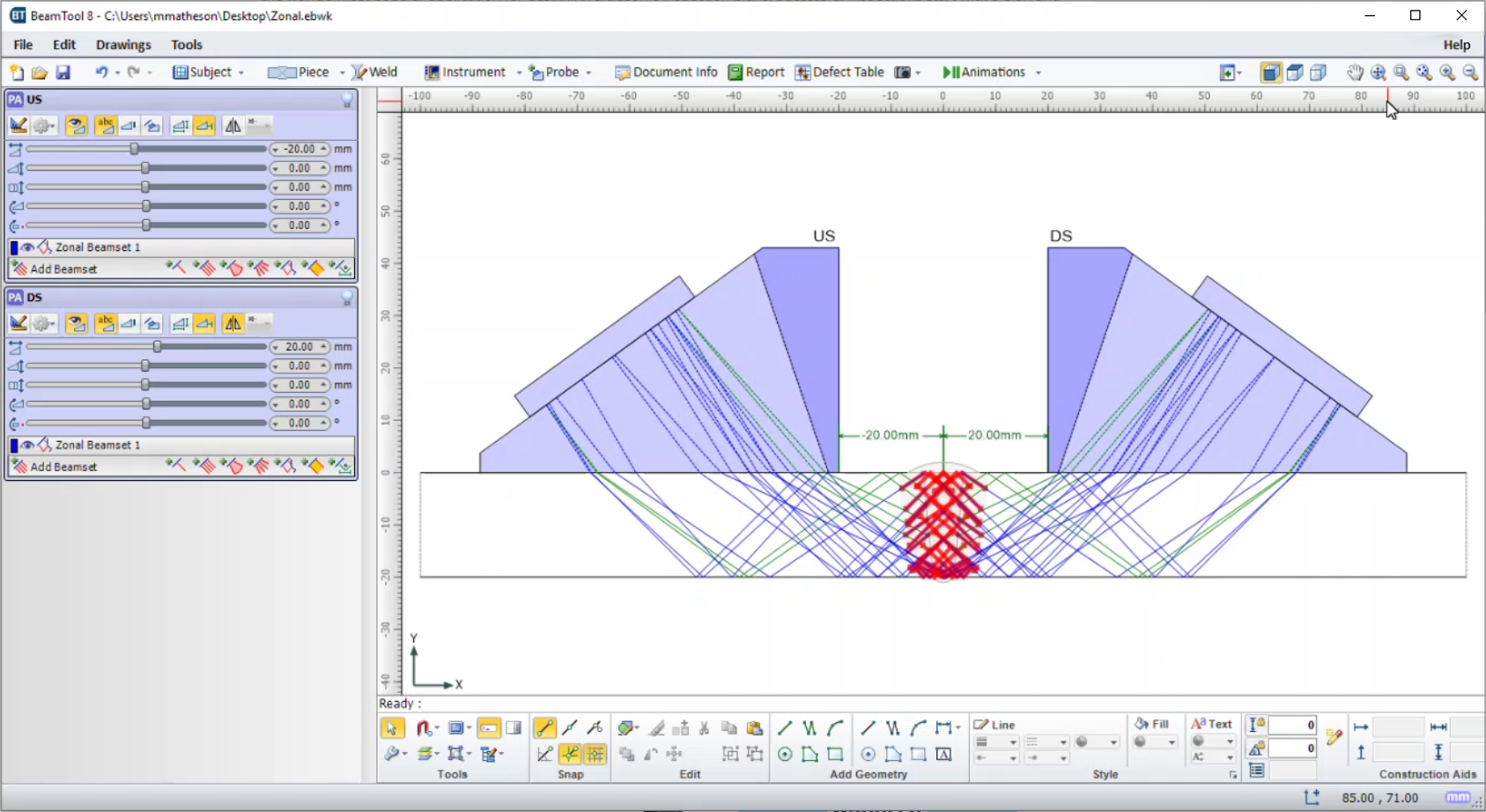
Zonal Discrimination
BeamTool ZONAL Add-on provides the ability to define Weld Zones, which are used in conjunction with a Zonal Beamset to provide automated targeting of individual phased array beams into specific locations along the face of a weld bevel. The powerful new Beam Solver will then optimize the Focal Laws.

© Copyright 2000-2025 COGITO SOFTWARE CO.,LTD. All rights reserved