|
|
|
|
|
|
|
S5 for Windows ® Version 7
New in Version 7:
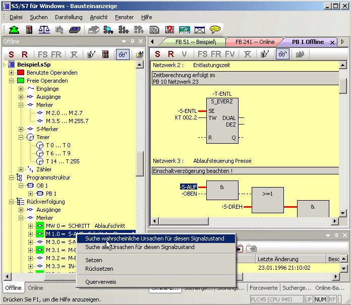
S5 for Windows® provides the tools for creating, modifying, testing and documenting programs for programmable logic controllers (PLC). S5 for Windows® is designed for programming the Siemens PLC family SIMATIC S5 with STEP5. The Function Block Diagram (FBD), the Ladder Diagram (LAD) and the Statement List (STL) are used as presentations for S5. Existing S5 programs can be edited directly without im-/export. S5 for Windows® is compatible to the original Siemens programming unit. For automatic troubleshooting the S5 Doctor functions are integrated as well.
The OsciCAM® allows to analyze motion processes through synchronisation of previously recorded videos and process signals. Recorded videos can be shown synchronously to process signals and a recorded block status of the PLC with time stamp.
With the Statusrecorder, dynamic procedures can be expolored by subsequently analysis of the block status frame by frame. The Statusrecorder logs the block status and shows these with time stamp, permitting subsequent changing between the presentations STL, CSF and LAD.
With the Oscilloscope feature the diagnostic capabilities of the programming system are further enhanced. Dynamic processes can be monitored and analyzed in an integrated screen, in look and feel adapted from an oscilloscope front panel. Pointing to I/O signals with a virtual test probe is sufficient for monitoring multiple signals inside the virtual oscilloscope. Signal recording can be stopped at any time for further timing investigation of the machine fault. Besides watching I/O signals, also the state of local variables at a defined position of program execution can be watched, by simply pointing to the variable with the test probe in block status. Only the integration into the programming system S5 for Windows® makes this possible. The recorded data can also be saved for later investigation, for archiving purposes or to send the information via e-mail.
A comfortable editor to create and edit symbolic tables is integrated. Searching and replacing for any criteria as well as rewiring is possible. A syntax check is integrated. The new comfortable multiple segment editor for the creation of statement lists, function block diagrams and ladder diagrams allows the representation of complex functions too. Focus was set on the ease of use with the mouse and/or the keyboard. Cross references and/or the corresponding symbol files are shown with the correct addresses. In this window the symbol file can be edited simultaneously. The allocation
of new addresses with syntax check is integrated. Statement lists are created with the comfort of integrated editor. The Windows clipboard can be used for program or configuration manipulations in any place. Statement lists can be altered into function block diagram or ladder diagrams, as far as they are displayable. The display of Function Block Diagrams and Ladder Diagrams in form of State Statement Lists is always possible.
With S5 for Windows® multiple segments can be shown in the status display representations statement list, function block diagram and ladder diagram. The CPU status function provides information about interrupt stack, block stack and system data.
S5 for Windows® allows calling the COM packages. Communication to a PLC can be established via an USB adaptor. This function is suppoertd with the operating systems Windows 2000 and WindowsXP(32 Bit) only.
The G5 for Windows® Step Sequence Programming (now included within S5 for Windows®) is a tool for easy programming sequential steps (sequencer control) within a STEP5 PLC program. A Step Sequence programmed in a Step Sequence Block (SB) is made out of steps and transitions. The transitions logic is used to enable the following step.
The graphical G5 for Windows® Step Sequence Programming supports linear sequences, alternative branching, simultaneous branching and jumps. Steps are displayed with boxes. There is a differentiation between an initial step, a permanent step, and a selective step. The initial step is used for an unconditional start of the Step Sequence. The instructions of a permanent step will always be executed even if the step flag is not active. The instructions of a selective step will be jumped over if the step flag is not active.Transitions are displayed as lines. The following step will only be executed if the logic of a transition is true. With a simultaneous branch it is possible to branch up to eight (8) further steps. The graphical display of steps and transitions may include comments. With the exception of the initial step, each step may be assigned to a time. This could be a waiting time (delay timer) or a monitoring time (watch dog).
The G5 for Windows® Graphical Step Sequence programming is compatible to the SIEMENS GRAPH5 and GRAPH5/II PLC programming package and therefore it also needs the standard SIEMENS Function and Step Blocks (FB70/71 - SB0, FB72 - SB2, FB73 - SB3). Simultaneously to the actual Step Sequence the logic of the selected Step or Transition is displayed in a separate window. This logic may be displayed and edited inLadder logic (LAD), Control System Flowchart (CSF), or Statement List (STL). The size of the logic window may be adjusted. The corresponding Symbolic Library may also be displayed and edited at the same time. The size of the step boxes is adjustable to the size (number of characters per line, number of lines) of the used comments. The status display has the same layout as the editor window. Active and corrupted steps are specially indicated.
S5 for Windows® provides the tools for creating, modifying, testing and documenting programs for programmable logic controllers (PLC). S5 for Windows® is designed for programming the Siemens PLC family SIMATIC S5 with STEP5. The Function Block Diagram (FBD), the Ladder Diagram (LAD) and the Statement List (STL) are used as presentations for S5. Existing S5 programs can be edited directly without im-/export. S5 for Windows® is compatible to the original Siemens programming unit. For automatic troubleshooting the S5 Doctor functions are integrated as well.
A comfortable editor to create and edit symbolic tables is integrated. Searching and replacing for any criteria as well as rewiring is possible. A syntax check is integrated. The new comfortable multiple segment editor for the creation of statement lists, function block diagrams and ladder diagrams allows the representation of complex functions too. Focus was set on the ease of use with the mouse and/or the keyboard. Cross references and/or the corresponding symbol files are shown with the correct addresses. In this window the symbol file can be edited simultaneously. The allocation of new addresses with syntax check is integrated. Statement lists are created with the comfort of integrated editor. The Windows clipboard can be used for program or configuration manipulations in any place. Statement lists can be altered into function block diagram or ladder diagrams, as far as they are displayable. The display of Function Block Diagrams and Ladder Diagrams in form of State Statement Lists is always possible.
The OsciCAM® allows to analyze motion processes through synchronisation of previously recorded videos and process signals. Recorded videos can be shown synchronously to process signals and a recorded block status of the PLC with time stamp.
With the Statusrecorder, dynamic procedures can be explored by subsequently analysis of the block status frame by frame. The Statusrecorder logs the block status and shows these with time stamp, permitting subsequent changing between the presentations STL, CSF and LAD.
With the Oscilloscope feature the diagnostic capabilities of the programming system are further enhanced. Dynamic processes can be monitored and analyzed in an integrated screen, in look and feel adapted from an oscilloscope front panel. Pointing to I/O signals with a virtual test probe is sufficient for monitoring multiple signals inside the virtual oscilloscope. Signal recording can be stopped at any time for further timing investigation of the machine fault. Besides watching I/O signals, also the state of local variables at a defined position of program execution can be watched, by simply pointing to the variable with the test probe in block status. Only the integration into the programming system S5 for Windows® makes this possible. The recorded data can also be saved for later investigation, for archiving purposes or to send the information via e-mail.
With S5 for Windows® multiple segments can be shown in the status display representations statement list, function block diagram and ladder diagram. The CPU status function provides information about interrupt stack, block stack and system data.
S5 for Windows® allows calling the COM packages. Communication to a PLC can be established via an USB adaptor.
The G5 for Windows® Step Sequence Programming (now included within S5 for Windows®) is a tool for easy programming sequential steps (sequencer control) within a STEP5 PLC program. A Step Sequence programmed in a Step Sequence Block (SB) is made out of steps and transitions. The transitions logic is used to enable the following step. The graphical G5 for Windows® Step Sequence Programming supports linear sequences, alternative branching, simultaneous branching and jumps. Steps are displayed with boxes. There is a differentiation between an initial step, a permanent step, and a selective step. The initial step is used for an unconditional start of the Step Sequence. The instructions of a permanent step will always be executed even if the step flag is not active. The instructions of a selective step will be jumped over if the step flag is not active.Transitions are displayed as lines. The following step will only be executed if the logic of a transition is true. With a simultaneous branch it is possible to branch up to eight (8) further steps. The graphical display of steps and transitions may include comments. With the exception of the initial step, each step may be assigned to a time. This could be a waiting time (delay timer) or a monitoring time (watch dog). The G5 for Windows® Graphical Step Sequence programming is compatible to the SIEMENS GRAPH5 and GRAPH5/II PLC programming package and therefore it also needs the standard SIEMENS Function and Step Blocks (FB70/71 - SB0, FB72 - SB2, FB73 - SB3). Simultaneously to the actual Step Sequence the logic of the selected Step or Transition is displayed in a separate window. This logic may be displayed and edited inLadder logic (LAD), Control System Flowchart (CSF), or Statement List (STL). The size of the logic window may be adjusted. The corresponding Symbolic Library may also be displayed and edited at the same time. The size of the step boxes is adjustable to the size (number of characters per line, number of lines) of the used comments. The status display has the same layout as the editor window. Active and corrupted steps are specially indicated.

© Copyright 2000-2023 COGITO SOFTWARE CO.,LTD. All rights reserved