CAD .NET is a library for developing solutions in .NET environment. It supports AutoCAD® DWG/ DXF, PLT and other CAD formats.
The library can be used in a wide range of spheres:
CAD .NET provides users with the following basic features that can be used in the project under development:
The table shows CAD .NET supported formats:
CAD .NET provides users with the control elements inherited from Windows Forms to display CAD drawings. Usually such elements are located at Windows Form but they can also be located at the WPF page. If you need an ASP .NET based Web Control, it can be provided additionally.
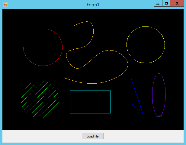
The CADPictureBox class is the basic implementation of the control element for displaying vector drawings. Visually CADPictureBox includes only area for drawing visualization and can be extended by the necessary control elements in the project under development. EditorDemo is an example of the project using CADPictureBox.

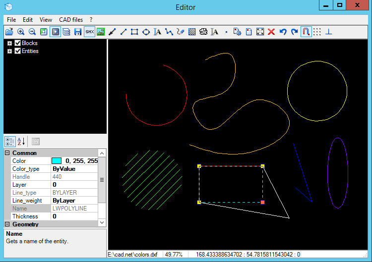
The CADEditorControl class includes implementation of the required event and settings handlers. To start working with it it is enough to place such a control element in the form. CADEditorControl includes panning, zooming, visual entity selection as well as allows using such features as visual entity creating, visual editing with the help of markers and the Properties window, snap, grid and ortho modes. The EditorControl demo shows how to use this control element.

CAD .NET can be used for development of the software that prepares data for CNC machines. DXF format supported by the library is one of the most frequently used file formats for processing two-dimensional surfaces. Access to drawings data enables users to get all the information necessary for processing.
The library also makes it possible to transform entities including conversion of the source drawing texts into polylines with high precision of curved line segment. For example such a feature can be useful for laser processing.
We will be glad to answer all your questions concerning the library and will help you to choose the most convenient license option.
If you haven’t found any features necessary to implement your task, we will be glad to discuss custom enhancements.
Inherited classes structure is the basis of the CAD .NET library interface. You can find short descriptions of the most important classes below.
The CADImage class defines the drawing object. All available drawing data can be received via properties of this class. To create a new drawing it is necessary to create and initialize the CADImage object:
CADImage cadImage = new CADImage();
cadImage.InitialNewImage();
When this code is implemented a new drawing is ready for entities adding.
The library includes the CADImage derived classes that must be used only to import drawings of the corresponding format:
The CADImage.Layouts collection contains all drawing layouts while CADImage.CurrentLayout provides access to the current drawing layout, i.e. to the layout that will be visualized.
To draw the conclusion, here’s an example showing how to create a new drawing and add the CADLine entity (a line) to it:
CADImage cadImage = new CADImage();
cadImage.InitialNewImage();

CADLine vLine = new CADLine();
vLine.Point = new DPoint(80, 100, 0);
vLine.Point1 = new DPoint(150, 150, 0);
vLine.Color = Color.Blue;
vLine.LineWeight = 0.3;

cadImage.Converter.Loads(vLine);
cadImage.CurrentLayout.AddEntity(vLine);
When this code is processed, the current drawing layout can be visualized with the help of the CADImage.Drawmethod.
The basic CADImage class is used to import DXF drawings.
While importing we recommend to use the CADImage.CreateImageByExtension function to create the required class automatically (it is defined by the text parameter extension). The next code automatically initializes cadImage as the class object of the required format (DWGImage) and then imports the specified drawing.
CADImage cadImage = CADImage.CreateImageByExtension(@"d:/1.dwg");
cadImage.LoadFromFile(@"d:/1.dwg");
It is unnecessary to implement the initialization method while importing the existing drawing.
The CADConverter class contains drawing settings as well as entries related to any existing drawing objects. Such nonvisual objects as layers, blocks and styles are stored in the CADConverter object. Each drawing has an only CADConverter object access to which is carried out via the CADImage.Converter. When any new object is added or any existing one is edited, a new/edited object must be loaded to CADConverter: :
cadImage.Converter.Loads(changedObject);
The CADEntity class is the basic entity class of the drawing (in other words, class of visual entities) as well as of other objects (e.g. layers and blocks). Each entity has its own set of properties and it allows users to access graphical drawing data more efficiently.
The CADEntityCollection class presents a collection of entities (CADEntity objects and inherited classes). Access to entity members can be carried out not only by index but also by Handle (a unique identifier for each entity).
The CADLayout class is the CADEntity derived class and presents a nonvisual layout object where entities are located. CAD .NET groups entities according to the layouts where they are located. Layout entities are contained inCADLayout.Entities that is the object of CADEntityCollection.
The CADImage.Layouts collection contains all drawing layouts while CADImage.CurrentLayout provides access to the current drawing layout, i.e. to the layout that will be visualized.
To draw the conclusion, here’s an example showing how to create a new drawing and add the CADLine entity (a line) to it:
CADImage cadImage = new CADImage();
cadImage.InitialNewImage();
CADLine vLine = new CADLine();
vLine.Point = new DPoint(80, 100, 0);
vLine.Point1 = new DPoint(150, 150, 0);
vLine.Color = Color.Blue;
vLine.LineWeight = 0.3;
cadImage.Converter.Loads(vLine);
cadImage.CurrentLayout.AddEntity(vLine);
When this code is processed, the current drawing layout can be visualized with the help of the CADImage.Drawmethod.
© Copyright 2000-2025 COGITO SOFTWARE CO.,LTD. All rights reserved