CYPECAD

Reliable structures, very precise drawings
CYPECAD was brought about to carry out the analysis and design of reinforced concrete and steel structures, subject to horizontal and vertical forces, for houses, buildings and civil work projects.
Its use guarantees maximum analysis reliability and the best drawing design, including the following elements:
Floor slabs
Joist floor slabs can be composed of concrete (generic), precast reinforcement, precast prestressed, in situ, steel (T and double T sections), truss joists and timber. The deflection is calculated in all cases.
Additionally, it allows for flat and solid slabs, waffle slabs, hollow core slabs, and composite slabs (steel deck) to be used.
Beams
The floor beams may be reinforced concrete, steel (normal or castellated), mixed and timber. Corbels can also be introduced.
Supports
The program allows for reinforced concrete columns, steel columns and composite steel and concrete columns.
Shear walls can be rectangular or adopt on plan any shape made up of rectangles.
Walls may or may not have lateral pressures and may be reinforced concrete, generic load bearing or concrete block walls with or without reinforcement (the dimensions of the blocks are introduced by the user or from manufacturer catalogues such as NORMABLOC National Association of Concrete Blocks and Masonry Manufacturers).
Walls may contain openings. The program calculates the necessary additional reinforcement of the openings in the reinforced concrete walls (lintel, guardrail, lateral and diagonal) and the lintel reinforcement when the gaps are introduced in concrete block walls. Additionally, it is possible to obtain a report of the checks that are carried out in the analysis on this reinforcement and can be viewed on screen or printed out.
The crown beam is also designed for all types of walls as is the intermediate beam at floor level in the case of generic load bearing walls and concrete block walls.

Stairs
CYPECAD analyses and designs stair slab reinforcements as isolated elements of the structure. Depending on the geometry, type and support arrangement and the applied gravitational loads, the program establishes the reactions on the main structure, which are applied as line and surface loads (in the case of steps built on the slab) in their corresponding permanent and live load cases.
The program calculates the stairs by finite elements, taking into account the usual two load cases for the stair analysis: permanent loading and live loading.
CYPECAD displays on screen the reinforcement of each of the spans making up the stairwell. It is also possible to consult, in a three dimensional view, the displacements, forces and see the deformed shape of each span.
Foundations
The foundation can be fixed (by pad foundations or pile caps) or ‘floating’ (with slabs on grade and foundation beams, having to define the subgrade modulus upon applying the Winkler theory).
The foundations may also be designed by having only introduced column starts.
Isolated or combined pad foundations may be composed of reinforced concrete or mass concrete and may support multiple columns.
Pile caps can hold a multiple number of piles. A wide range of options are available:


Both the pad foundations and pile caps allow for several columns and shear walls to be placed on them without restraining their position on the foundation element.
The strap beams also act on the pile caps and the tie beams brace the elements.
Base plate design is carried out for any steel column arrangement (simple sections and composite sections).
General data
Wind and earthquake (spectral mode analysis) loads are selected, by selecting the properties as described in the codes. In both cases second order effects (P-delta) may be taken into account.

There is no limit as to how many load cases, line, surface or point loads can be applied and at which position.
The program automatically generates any load case combination defined by the user in accordance with the conditions that have been indicated (compatible, incompatible or simultaneous). For example, the load case combination of a load composed of a generic live load and the action of a truck load at various positions is generated automatically. The positions of the truck are incompatible amongst one another but compatible with the generic live load and the remaining load cases of a different nature.
Users can also define their own project situations to personalize the combinations that are going to be used in the corresponding analysis of the structural elements of the job.
This has been adapted for national and international codes.
CYPECAD has numerous analysis options, with explanations and on screen graphs, to personalize
the analysis, design and reinforcement by means of tables.
Data entry (Structure geometry)
The geometrical introduction of a job in CYPECAD is carried out on plan views on each of the different levels of the structure, the same way as drawings are visualized out on site and so avoiding three dimensional data introduction which is much more complex.
With CYPECAD the data of the structure can be introduced in three different ways:
When introducing a structure you may use any of the three methods mentioned above.
CYPECAD also allows for the job to be exported to IFC format. To do so, the user license does not necessarily have to include the "Automatic job introduction: DXF, DWG and CAD/BIM models" module.


When introducing a structure you may use any of the three methods mentioned above.
Any of the three methods may be combined during the introduction of a structure:
The beam manager allows for the beams that are going to be introduced to be straight or curved, and their introduction mode can be continuous or discontinuous. DXF or DWG displacements and adjustments are possible during beam entry or once they are situated on plan. You may also add as many floors, columns, beams or panels as you wish.
If you have acquired the automatic job introduction module, not only will you be able to adjust beams to DXF or DWG lines, but also to open or closed polygons in these drawing files.
It obtains the 3D view, solid and immediate (with conical or isometric perspective) of any floor or of the entire building, without the need of having to previously analyze the job.
It is possible to move around freely inside the structure when it is visualized with conical perspective. In the 3D view, the floors and walls possess a degree of transparency making it easier to visualize those elements that remain hidden.
Both horizontal or inclined slabs may be introduced. Inclined slabs are simple to introduce as only the inclined plane has to be defined. This can be done by defining 3 level points, by a given slope line or by the maximum slope line. This slope is then assigned to panels that have been previously introduced horizontally and hence avoiding a complex 3D introduction.
It is possible to copy all the geometry of a floor from one floor to another, as can the properties of a panel (including the insertion point) to another panel on the same or different floor.
Integrated 3D structures (Connection between CYPECAD and CYPE 3D)
CYPECAD and CYPE 3D are connected by means of the Integrated 3D structures, which allow for a structure to be included in CYPECAD with the same design assumptions as it would have in CYPE 3D.
An integrated 3D structure is a steel, aluminium or timber structure, made up of nodes and bars with six degrees of freedom which is connected and bonded to the main building structure managed by CYPECA
The integrated 3D structures of CYPECAD is not technically a module: to be able to define the integrated structures, the user has to have the license to use both CYPECAD and CYPE 3D. Several integrated 3D structures can be added to a single CYPECAD project.
An integrated 3D structure is connected to the CYPECAD structure by means of connection points which may be situated on the following CYPECAD elements: columns, column starts (where a pad footing or pile cap can be defined later on), beams, flat slabs, waffle slabs, mat foundations or foundation beams.
CYPECAD allows for an Integrated 3D structure to be introduced in two different ways:

Analysis
The analysis of the structure is carried out by means of a 3D spatial analysis using stiffness matrix methods, making up all the elements defining the structure: columns, reinforced concrete shear walls, walls, beams and slabs. Having finished the analysis, the various elements may be checked for errors.
The seismic analysis is undertaken by means of a complete modal spectral analysis which resolves each mode as a load case and carries out the modal expansion and the modal combination to obtain the forces.
Capacity design criteria for seismic design of concrete columns and beams
When CYPECAD carries out a seismic analysis, the program takes into account the capacity design criteria for concrete beams and columns of some specific design codes.
These capacity design criteria are specified in the Detailed Ultimate Limit State reports for concrete beams and columns.
For CYPECAD to take into account the capacity design criteria of the indicated seismic codes, each code must be compatible with the concrete code that has been selected for the job and be able to use the advanced column and beam editors.
Capacity design criteria for seismic design of concrete floor slabs
The geometric and mechanical properties of the columns and beams are automatically contemplated with the capacity checks as are, optionally, the properties of the floor slabs bearing on beams reaching a column.
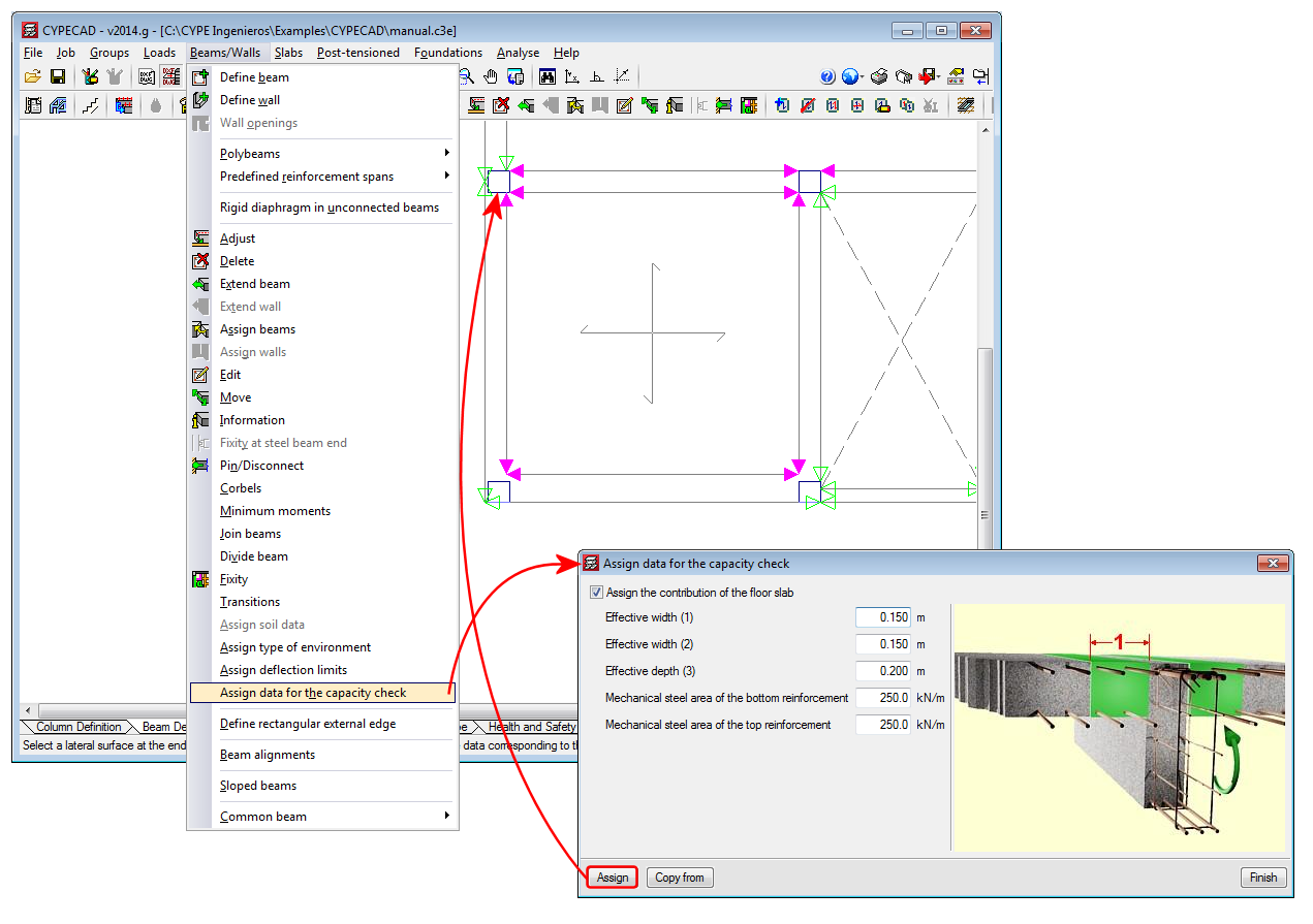
To define the geometric and mechanical properties of the floor slabs, with regards to the capacity checks for concrete beams and columns, a new option has been implemented in the program: Assign data for the capacity check (Beam Definition tab > Beams/Walls).
The aforementioned option will only be visible if a seismic analysis is carried out with a design code which has the capacity check implemented for CYPECAD .
When this option is activated, a dialogue box appears where users can define the following data:
Users can assign them freely to any side or end of beams reaching columns. This way, slabs which have different geometric or mechanical properties at either side of the beam, or beams which only have the floor slab on one side can be contemplated.
To identify each of the sides and ends of the beam to which the data has been assigned for the capacity checks, the program displays small magenta triangles at these zones, which are displayed when the option Assign data for capacity check is selected. The triangles will be displayed in green at zones where the properties of the slab have not been assigned, in which case, the dimensions and steel areas of the slab will not intervene in the capacity checks for the concrete beams and columns.

Seismic analysis with force amplification in open floors or with partitions that are less rigid than on other floors
It is vitally important to consider the effect non-structural elements (façades and partitions) have on the behavior of a building exposed to seismic action, especially when open floors are present or a floor contains partitions and façades that are less rigid than those on other floors.
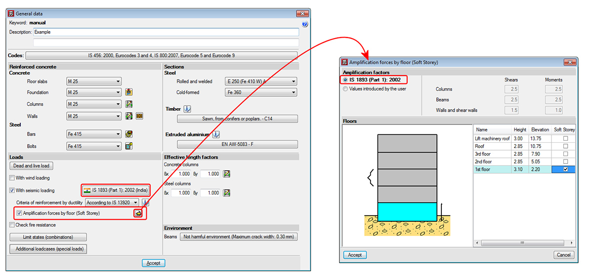
There are design codes that oblige project designers to contemplate the absence or reduction of the stiffness of the partitions and façades on specific floors, by applying moment and shear amplification factors to columns, beams, walls and shear walls situated on floors with less stiffness than the rest when resisting the horizontal displacements caused by seismic action. Examples include IS 13920 (India) -Soft Storey- or Proyecto de Reglamento CIRSOC 103-2008 (Argentina). Logically, the tendency of standards and codes which do not contemplate these effects is to gradually take them into account.
The 2013.l version of CYPECAD allows for moment and shear amplification factors to be applied to columns, beams, walls and shear walls situated on floors chosen by users, regardless of the selected code. To do so, the option Amplification forces by floor has been implemented n the General data dialogue box (Job > General data). Upon activating this option, a dialogue box appears with the same name. If the selected code contemplates the reduced floor stiffness effect due to weaker partitions, the program displays the corresponding moment and shear force amplification factors, which are then applied to the selected floors. Users also have the choice to indicate their own amplification factors. If the selected code does not contemplate these effects, the program allows users to introduce the values they wish for the floors they select.
This method to consider the effect the absence of partitions and façades on specific floors may have when exposed to seismic action, is an approximation to the real behavior of the building.

Interaction of the structure with the construction elements
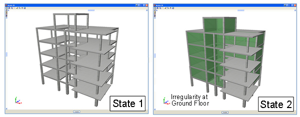
CYPECAD contains a software tool which allows for a dynamic analysis to be carried out on buildings with seismic loads acting upon them, which includes the effects of the non-structural construction elements used in the façades and partitions of the building, and considers various behavioural models of the building corresponding to different situations or states of these elements.
The façades and partitions of the building are considered as being “non-structural” elements, however, during an earthquake, they do provide stiffness to the structure, hence modifying the distribution and magnitude of the forces caused by the seismic action For example, when there is a non-uniform distribution between floors of the stiffness associated with the partitions, the horizontal forces have a greater impact on the columns belonging to the floors with less stiffness, producing shear forces of a high magnitude in the columns. If these have not been designed accordingly, the forces can cause a fragile fracture, endangering the stability of the building, even leading to its collapse.

There are currently no software tools available on the market for the structural analysis of buildings which integrate the possibility of considering, in a simple manner, the façades and partitions, even though it has been proved that they directly affect the stability, stiffness and safety of the building during an earthquake. Since this CYPECAD module does integrate them, keeping the computation periods within an admissible period, their integration in the building projects will increase their quality and the safety of their occupants, allowing for unfortunate losses, both material and human, to be avoided after an earthquake.
Analysis using multiprocessors
CYPECAD and CYPE 3D offer the use of multiprocessors during their analysis.
To acquire these tools, CYPECAD and CYPE 3D have two new common modules which allow for substantial periods of time to be saved during the analysis:

Export to TEKLA® Structures and in CIS/2
Once the structure has been analyzed, the columns, beams and construction details containing the designed joints (using the Joints I, Joint II and Joints III modules) of CYPECAD and its Integrated 3D structures can be exported to TEKLA Structures and in CIS/2 format. Concrete columns and beams are exported as generic bars, whilst steel columns and beams are exported as is done in CYPE 3D.
Export to IFC format
CYPECAD allows for all the structural elements which have been designed by the program (except corbels) to be exported to IFC format (Industry Foundation Classes). This way, the information that has been introduced and generated in CYPECAD can be read in CAD/BIM programs such as Allplan®, Archicad®, Revit® Architecture, etc.
To carry out the export, an option has been implemented in CYPECAD: Export to IFC format (File > Export).
Within the Export to IFC dialogue box (File > Export > IFC), users can choose amongst four IFC format variations for generating the export file:
In the export process, CYPECAD assigns different colours to the materials of the structural elements which are exported (concrete, steel, aluminium, timber, masonry walls, generic bars from integrated 3D structures). When exporting to Archicad, textures are also generated for each material.
The export to IFC format includes the different types of joists (reinforced, prestressed, in situ, steel and open-web joists) present in joist floor slabs. These are also represented in the 3D views provided by CYPECAD.
CYPECAD also allows for IFC format files, which have been generated by CAD/BIM programs to be imported, thanks to the Automatic job introduction: DXF, DWG and CAD/BIM models module. For CYPECAD to export the job to IFC format, users are not required to have the "Automatic job introduction: DXF, DWG and CAD/BIM models" module.
Results
There are many tools available to be able to check all the graphical results on screen.
After the analysis it is possible to visualize the deformed shape of the structure in 3D (with a color scale), produced by the simple load cases or by a combination of load cases, including earthquake loading. It is also possible to observe an animation of the deformation process produced by the selected load case combination.
The displacements, forces, force combinations and steel areas of flat and solid slabs, slabs on grade and waffle slabs can be represented by contour maps (coloured diagrams in which each colour represents a value) and in contour line diagrams (curves that joint geometric points with the same value).
It also carries out a graphical consultation of envelopes, deflections, etc.
The reinforcement of all the elements can be modified with a subsequent check in foundation pads, pile caps, beams, columns and joist floor slabs.
With the beam reinforcement editor a complete visualization of the frame is obtained where the user can graphically modify the results, add, delete, join and divide longitudinal bars and links as well as being able to modify their lengths and anchorage lengths.
It is possible to copy reinforcement amongst frames of the same or different floors and group frames in the same floor before and after the analysis.
The user may automatically equalize all the top reinforcement of joist floor slabs by length or bar size and length. This way, a more uniform reinforcement is obtained and, therefore, easier to place on site.
The program modifies waffle slab and flat slab reinforcement by means of view tables. The reinforcement can be copied from one floor to another, modify the geometry after the analysis and introduce reinforcement without analyzing.
Editing of foundation pads, pile caps, base plates and strap and tie beams results to be a powerful tool allowing the check to be carried out of any geometry and reinforcement defined by the user. A report can be obtained of all the checks carried out on the foundations and view its compliance factor.
It is possible to equalize the geometry, type and reinforcement of pad foundations, pile caps, strap and tie beams and base plates.
Drawings
Project drawings can be configured with different formats and paper sizes (standard or user defined). Additionally, these can be drawn by printer, plotter or exported to DXF or DWG format. It is possible to include the DXFs or DWGs that have been used to define the job in the floor drawings. All of the drawings can be integrated or only those layers that are deemed necessary, such as stairs.

In the floors of the job, a drawing editor is available, which allows multiple resources to be used: add dimensions, texts, building sections, construction details in DXF format, floor slab sections, modify text positions, etc. These modifications are saved with the project.
CYPECAD possesses a vast library of construction details: steel, concrete, mixed and inclined slab, available to incorporate to any of the drawings generated by the program. You may also acquire this library edited in two volumes that includes the details in DXF and DWG format.
You may apply any scale, line thickness, font size, frame etc., this way you may completely personalize the drawing.
CYPECAD provides complete and clear drawings. You may obtain layout, floor plan, foundation, beam, column schedule, and column and shear wall detail, foundation loads, wall elevation, stair, load, corbel, etc. drawings. They optionally include take off and reinforcement detail tables. They can be configured so that our users obtain the drawing adjusted to each of their needs. CYPECAD has an incorporated editor that allows to move the texts whilst the drawing is being visualized on screen.
You may easily obtain reports of all the introduced data and of the results: job data report, combinations used in the analysis, foundation, corbel, envelopes, reinforcement and take-off of all the elements, job take-off, horizontal wind loads, participation coefficients (earthquake loading), second order effects, etc. All this is obtained on screen or printed out, but you may also create files in HTML, DXF, DWG, RTF, PDF, etc. format.
Detailed ultimate limit state check reports
CYPECAD, CYPE 3D and the Integrated 3D structures of CYPECAD generate detailed reports on the ultimate limit state checks of steel and aluminium sections.
These reports contain all the checks carried out by the program to design the structures and constitute an important document with which the user can:
The level of detail of these reports also acts as a detailed guide so the user can know all the checks the section is submitted to.
CYPECAD versions
CYPECAD is available in its unlimited version and also in two limited versions called LT30 and LT50, which contain the same tools and module acquisition possibilities, but have the following conditions:
CYPECAD LT50:
CYPECAD LT30:
Integrated 3D structures of CYPECAD (also LT50 and LT30) is not technically a module. To define these 3D structures in CYPECAD, users must also have the required permits to use CYPE 3D in their user license and, optionally, modules which are exclusive to CYPE 3D.

© Copyright 2000-2025 COGITO SOFTWARE CO.,LTD. All rights reserved