010-68421378
sales@cogitosoft.com
Your location:Home>News Center >Industry News

CADEditorX--How To Create and Process XML

latest update:2022/04/19 Views:460
XML can be created as a simple string with the help of any programming language This is the most simple way that can be recommended for initial investigation and for many projects where there is no need to handle complicated XML files.


There are two ways allowing creating and processing XML format.

XML as simple string

XML can be created as a simple string with the help of any programming language This is the most simple way that can be recommended for initial investigation and for many projects where there is no need to handle complicated XML files.

A simple way to work with CAD XML API:

1. Look at the example XML files and How to help section.

2. Create XML strings on the basis of demo examples to implement the required features.

3. You can either load XML files from HDD or add all these XML texts as string constants directly to the application source code.

We recommend to use the Format() function (which is present in all popular programming languages) to insert data to XML strings.

C# example for calling line:


        string command =

            @"<?xml version=""1.0"" encoding=""UTF-8""?>

              <cadsofttools version=""2.0"">

                <command text=""Line""/>

              </cadsofttools>";

  string result = CADEditorX.ProcessXML(command);

XML obtained with the help of the OnProcess callback function can be also parsed using the common functions used to parse strings in your programming language.

C# example for the OnProcess callback:


string result = CADEditorX.ProcessXML("");


XML Parser

There are many XML parsers that are suggested for all popular development languages. Microsoft Windows has the DOM technology for handling XML, which is very powerful but not very fast. There are a lot of simple and fast XML parsers that are suggested as opensource for many programming languages.

It is recommended to use XML parser to implement complicated tasks with the help of CAD XML API.


How to get information about entities

To get information about the entities located in the Model area execute the following XML:

<?xml version="1.0" encoding="UTF-8"?>
<cadsofttools version="2">
    <get PathName="BLOCKS;*Model_Space;"/>
</cadsofttools>


To get information about the entities located within the layout execute the following XML:

<?xml version="1.0" encoding="UTF-8"?>
<cadsofttools version="2">
    <get PathName="BLOCKS;*PAPER_SPACE;"/>
</cadsofttools>


Note: Name of the *PAPER_SPACE layout block is stated for the corresponding layout.


How to get layers, text style, etc.

To get the list of the drawing layers and view their properties execute the following XML:

<?xml version="1.0" encoding="UTF-8"?>
<cadsofttools version="2">
 <get PathName="TABLES;LAYER"/>                              
</cadsofttools>  


To get the list of the drawing text styles execute the following XML:

<?xml version="1.0" encoding="UTF-8"?>
<cadsofttools version="2">
 <get PathName="TABLES;STYLE"/>                              
</cadsofttools>  


How to reach functional which is implemented in CADEditorX / ABViewer via XML

These instruments work via the command line that can be used directly in the corresponding panel of the user interface.

The command instruction is used to call the functional via the CAD XML Interface.

Supported commands are described in the User Reference.

Example showing how to start drawing a line:

<?xml version="1.0" encoding="UTF-8"?>
<cadsofttools version="2.0">
   <!-- Runs command line  with line command-->
 <command text="line"/>
</cadsofttools>


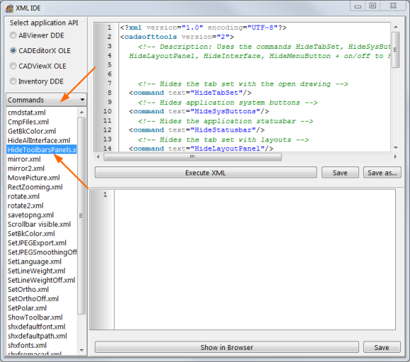
You can find examples of the most important command calls in the Commands section of the XML editor:


How to customize tab and panels

Question: Can I remove the Viewer, Editor, Advanced and Output default tabs? I want to create my own tabs with customized groups with existing buttons in them.
I want to retain these changes in ocx so that those will be the same when I open it again.

This is possible.

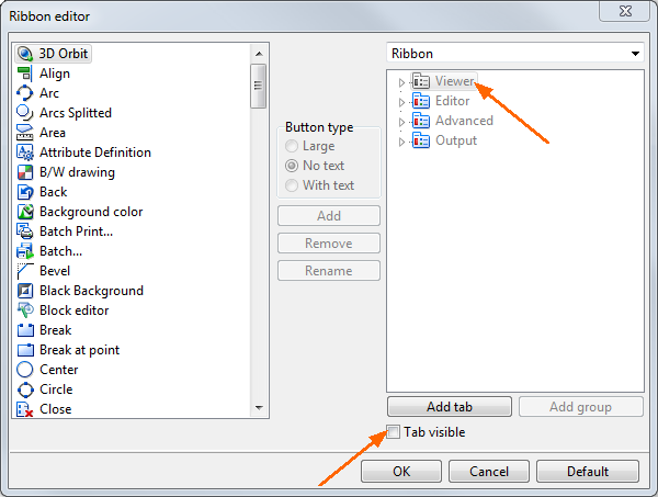
1. Click Customize ribbon in caption:


2. Deactivate the Tab visible option:


3. Repeat this for all the tabs.

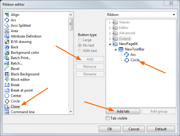
4. To add a new tab please click Add tab and you will see a new tab. You can change its name and add buttons from the left panel by selecting a button and clicking Add or double-clicking the button or dragging and dropping it to the panel:


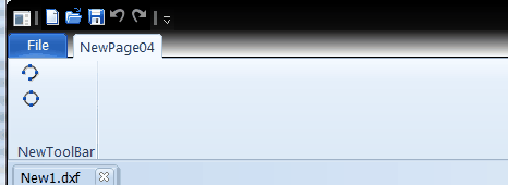
5. Click OK and you will see a toolbar like this:


Question: How is it possible to remove command line window via xml?

It can be done via the command line:

Commandline

Off.

Xml example:

<?xml version="1.0" encoding="UTF-8"?>
<cadsofttools version="2.0">
   <!-- Hide tab set with open drawing -->
 <command text="commandline"/>
 <command text="off"/>
</cadsofttools>


See the HideToolbarsPanels.xml to learn more about handling toolbars and panels.

When you execute the following code from HideToolbarsPanels.xml:

<?xml version="1.0" encoding="UTF-8"?>
<cadsofttools version="2.0">
   <!-- Hide tab set with open drawing -->
 <command text="HideTabSet"/>
   <!-- Hide application system buttons -->
 <command text="HideSysButtons"/>
   <!-- Hide application statusbar -->
 <command text="HideStatusbar"/>
   <!-- Hide tab set with layouts -->
 <command text="HideLayoutPanel"/>
   <!-- Hide Interface -->
 <command text="HideInterface"/>
   <!-- Hide menu button -->
 <command text="HideMenuButton"/>
   <!-- Hide Ribbon -->
 <command text="HideRibbon"/><command text="on"/>
</cadsofttools>

CADEditorX will look like this:


How to add line, text, block, layer, etc.

Such entities as lines, texts, mtexts, blocks and inserts and others as well as invisible objects like layers and styles are called Classes in CAD XML reference. They can be added by calling the add instruction that accepts CAD Drawing XML Structure as a child parameter.

There are a lot of examples of adding particular classes in the Classes section of the XML examples.

To add text and line execute the following XML:

<?xml version="1.0" encoding="utf-8"?>
<cadsofttools version="2">
 <add>
   <cstText Text="CADSoftTools" Point="0.5,0.5" Height="1"/>
   <cstLine point="0,0,0" Point1="10,0,0" color="0;1;"/>                
 </add>
 <fittosize/>
</cadsofttools>    


To add a new layer execute the following XML:

<?xml version="1.0" encoding="UTF-8"?>
<cadsofttools version="2">
 <add>
   <cstSectionTables Name="TABLES">
     <SubEntities>
       <cstTable Name="LAYER">
         <SubEntities>
           <cstLayer Name="New_Layer" color="0;3;"/>
         </SubEntities>
       </cstTable>
     </SubEntities>              
   </cstSectionTables>
 </add>
</cadsofttools>    


To add a block execute the following XML:

<?xml version="1.0" encoding="utf-8"?>
<cadsofttools version="2">
 <add>
   <cstSectionBlocks Name="BLOCKS">
     <SubEntities>
       <cstBlock name="block1">
         <SubEntities>
           <cstLine point="0,0,0" point1="50,0,0" />
           <cstText point="0,3,0" text="This is a block" height="3" />
         </SubEntities>
       </cstBlock>
     </SubEntities>
   </cstSectionBlocks>
   <!-- Add entities Model -->
   <cstInsert blockname="block1" point="0,50,0" layer="Layer2" />
 </add>
 <fittosize />
</cadsofttools>


How to add text in a box

Sometimes it is needed to mark up the drawing with text. Let us see how to create text in a box:


The following code example creates a rectangle, hatches inside it and adds the text.

<?xml version="1.0" encoding="UTF-8"?>
   <!-- Description: Example show how to create text in a box and how to use list of handles. -->
<cadsofttools version="2.0">
 <!-- Create simple rectangular Solid Hatch. Handle of polyline is saved as "@1" -->
 <add>
   <cstLWPolyline HandleSave="@1">    
   <SubEntities>                
   <cstVertex Point="0,0,0"/>      
   <cstVertex Point="2,0,0"/>
   <cstVertex Point="2,1,0"/>
   <cstVertex Point="0,1,0"/>
   <cstVertex Point="0,0,0"/>      
   </SubEntities>
   </cstLWPolyline>
 </add>
   <!-- Select polyline -->
 <Select Handle="@1"/>    
   <!-- Create hatch -->
 <createhatch/>
   <!-- Set red color, it's index is 1 -->
 <apply Color="0;1;"/>
 
<add>  
   <!-- Create text in box -->
   <cstMText Point="0.2,0.6" Height="0.2" TextValue="Text in a box" HandleSave="@2"/>
</add>                      
 <ShowSelectedEntities/>
   <!-- Handles can be accepted as a list with ";" separator -->
 <UnSelect Handle="@1;@2;$24"/>        
</cadsofttools>


What should be used as entity ID

Each Entity as well as each Class has a unique identification: 64bit digital Handle which stays the same after saving to file and changing the entity.

Handles are convenient IDs to work with the entities. For instance, we sign to the OnSelectEntity event:

<?xml version="1.0" encoding="UTF-8"?>
<cadsofttools version="2.0">
  <!-- Sign to OnSelectEntity event. Handle in result will be the last selected entity. All the selected entities can be accessed through calling "GetSelected" command, see GetSelected.xml -->
  <signtoevent Event="OnSelectEntity"/>
</cadsofttools>


When we click on any entity, we get its handle in the result parameter:

<cadsofttools version="2.0">
  <selectEntities>
     <result handle="$2B"/>
  </selectEntities>
</cadsofttools>  


After it we can use this handle handle="$2B" to work with the entity.

If we add the entity, the application creates a new Handle automatically and it is not possible to set Handle. This is the problem because when we add an entity, we do not know its handle.

Solution:

Use the HandleSave parameter with "@UniqueDigit"when you add an entity and then it can be called as the Handle alias.

Example, Add3.xml:

<?xml version="1.0" encoding="utf-8"?>
<cadsofttools version="2.0">
  <!-- Description: Example shows how to work with HandleSave -->  
  <add>    
     <cstText point="10,10,0" Text="HandleSave is @77" Height="3" HandleSave="@77" />  
  </add>            
  <!-- Handle alias @77 can be used for select and other instructions -->
  <select Handle="@77" />
  <apply Color="0;1;"/>    
  <FitToSize/>                      
  <!-- Sign to OnSelectEntity event. Handle in result will be the last selected entity. If you press entity which is created in this example, result will be its real Handle. -->
  <signtoevent Event="OnSelectEntity"/>
</cadsofttools>  


How to catch events

The SignToEvent instruction signs for particular events to accept callbacks with XML data.

Example for the OnSelectEntity event:

<?xml version="1.0" encoding="UTF-8"?>
<cadsofttools version="2.0">
   <!-- Sign to OnSelectEntity event. Handle in result will be the last selected entity.
   All the selected entities can be accessed through calling "GetSelected" command, see GetSelected.xml -->
 <signtoevent Event="OnSelectEntity"/>
</cadsofttools>    


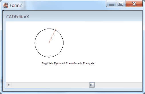
Run and select the entity by mouse. Result will be like:

<cadsofttools version="2.0">
 <selectEntities>
   <result handle="$26"/>
 </selectEntities>
</cadsofttools>    


Event examples are stored in the Events section that is marked at the left side:


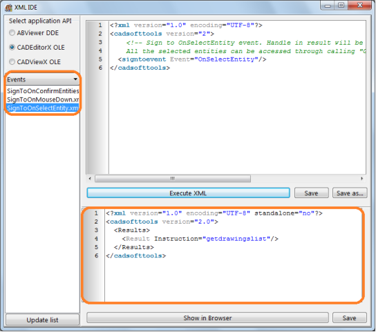
Result parameters are marked in the right bottom side of the screenshot.


How to add picture

Pictures are stored in cstImageEnt class. Please look at the following example.

<?xml version="1.0" encoding="UTF-8"?>
<cadsofttools version="2.0">
   <!-- Add entities -->
 <add>
 <cstSectionObjects Name="OBJECTS">
   <SubEntities>
     <cstDictionary name="IMAGEDEFS">
       <SubEntities>
         <!-- FileName="Specify the file path" -->
         <cstImageDef FileName="%SGSAMPLESPATH%\image.jpg"   HandleSave="@1"/>
       </SubEntities>  
     </cstDictionary>
   </SubEntities>
 </cstSectionObjects>
  <!-- Point - insertion point (corresponds to the bottom left corner of the image) -->
  <!-- Point1 - top left corner in the drawing coordinates (top left corner of the image) -->
  <!-- Point2 - bottom right corner in the drawing coordinates (bottom right corner of the image) -->
  <cstImageEnt Point="0,0,0" imagedef="@1">
    <Calc mode="0" Point1="0,100,0" Point2="100,0,0"/>
  </cstImageEnt>
 
  <cstImageEnt Point="0,0,0" imagedef="@1">
    <Calc mode="1" Width="100" Height="400" Angle="30"/>
  </cstImageEnt>
 
 </add>
   <fittosize />
</cadsofttools>      


How to add Hatch, filled rectangle or circle

Filled figures are implemented in the Hatch class that is created via the CreateHatch instruction. Also this can be linear hatched.  Please refer to the CreateHatch examples.

<?xml version="1.0" encoding="UTF-8"?>
  <!-- Description: Instruction CREATEHATCH creates Hatch using selecte entities as countours. Please select entity by mouse or by xml Instruction SELECT before calling this Instruction. -->
  <!--
     Syntax:
     <createhatch Hatchname="" Angle="" PatternScale="" Color=""/>
     Attributes:
     Hatchname - string - name of Hatch, default is "SOLID" which creates a solid hatch. Other names: "Box", "Escher" and others can be found in Hatch dialog in user interface.
     Angle - Double - rotation angle of hatch
     PatternScale - Double - scale of hatch's pattern
     Color - sring CADSoftTools color structure - color as index or RGB
  -->
<cadsofttools version="2.0">
  <!-- Create simple rectangular Solid Hatch. Handle of polyline is saved as "@1" -->
  <add>
     <cstLWPolyline HandleSave="@1">
       <SubEntities>    
          <cstVertex Point="140,100,0"/>
          <cstVertex Point="141,100,0"/>
          <cstVertex Point="141,103,0"/>
          <cstVertex Point="140,103,0"/>
       </SubEntities>
    </cstLWPolyline>
  </add>
 <!-- Select polyline -->
 <Select Handle="@1"/>
 <!-- Create hatch -->
 <createhatch/>
 <UnSelect Handle="@1"/>
 <!-- Create polyline for Hatch, -->
 <add>
   <cstLWPolyline HandleSave="@2">
   <SubEntities>    
   <cstVertex Point="141,109,0"/>
   <cstVertex Point="142,112,0"/>
   <cstVertex Point="143,109,0"/>
   <cstVertex Point="147,109,0"/>
   <cstVertex Point="144,107,0"/>
   <cstVertex Point="145,105,0"/>
   <cstVertex Point="142,107,0"/>
   <cstVertex Point="141,105,0"/>
   <cstVertex Point="141,107,0"/>
   <cstVertex Point="138,108,0"/>
   <cstVertex Point="141,109,0"/>
   </SubEntities>
   </cstLWPolyline>
 </add>
   <!-- Select polyline -->
 <Select Handle="@2"/>
   <!-- Create hatch -->
 <createhatch hatchname="BOX" Angle="30" PatternScale="0.1" Color="0;34;"/>
 <UnSelect Handle="@2"/>
 
 <!-- Create and select some countours for creating hatch. -->
 <add>
   <cstLine point="120,120,0" point1="130,130,0" Color="0;3;" HandleSave="@3"/>
   <cstLine point="120,120,0" point1="130,110,0" Color="0;3;" HandleSave="@4"/>
   <cstLine point="130,110,0" point1="130,130,0" Color="0;3;" HandleSave="@5"/>
   <cstCircle point="100,100,0" radius="10" Color="0;3;" HandleSave="@6"/>
 </add>
   <!-- Select contours -->
 <Select Handle="@3"/>
 <Select Handle="@4"/>
 <Select Handle="@5"/>
 <Select Handle="@6"/>
 <createhatch hatchname="SOLID" Color="0;3;"/>
 <UnSelect Handle="@3"/>
 <UnSelect Handle="@4"/>
 <UnSelect Handle="@5"/>
 <UnSelect Handle="@6"/>
 
 <fittosize />
</cadsofttools>


How to access CAD data from drawing

Please use the <get/> instruction to access CAD Drawing Database that will be returned by the OnProcess callback function.


How to ask for confirmation before a deletion

There are two ways of “confirming the deletion”

1. Library will ask before deleting entities, handles of which are specified in the <CustomSelectMode> parameters:

<?xml version="1.0" encoding="utf-8"?>
<cadsofttools version="2.0">
<CustomSelectMode AskOnDelete="True" Handle="$2C"/>
</cadsofttools>


2.  Event="OnConfirmEntitiesDeletion"

Event allows to control it from your application if you wish to delete an entity or not.

<?xml version="1.0" encoding="UTF-8"?>
<cadsofttools version="2">
   <!-- Sign to OnConfirmEntitiesDeletion event. Result is handles list of deleted entities.
        The entities deletion works only by xml commands. -->
 <signtoevent Event="OnConfirmEntitiesDeletion"/>
</cadsofttools>


When the user wants to delete an entity, CADEditorX will not delete it, just the event will be called with the result like here:

<cadsofttools version="2.0">
 <ConfirmEntitiesDeletion>
   <result handle="$2C"/>
 </ConfirmEntitiesDeletion>
</cadsofttools>


In this event our demo (not CADEDitorX itself!) shows message like this:


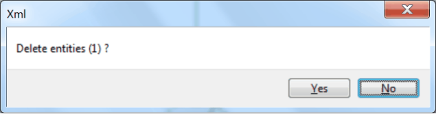
And after clicking “Yes” it runs xml to delete the selected entities:

<?xml version="1.0" encoding="UTF-8"?>
<cadsofttools version="2">
 <delete/>
</cadsofttools>


So, you can activate such a dialog in your application and delete entities after pressing OK” in YOUR confirmation dialog.


How to work with editor instruments “move”, “rotate”, “scale”, etc. from XML?

Question:  How to work with editor instruments “move”, “rotate”, “scale”, etc. from XML?

These instruments work via the command line. The supported commands are described in the User Reference.

Example of XML for rotating the entity. Entity should be selected by mouse or by  the selectentity instruction:

<?xml version="1.0" encoding="UTF-8"?>
<cadsofttools version="2.0">
   <!-- Runs command line  with rotate command-->
 <command text="rotate"/>
   <!—Base point -->
 <command text="1,1"/>
 <command text="Angle"/>
   <!—Angle value -->
 <command text="30"/>
</cadsofttools>


How to work with commands with dialogs: open, save, findtext, etc

Question:  how to work with commands with the dialogs: open, save, findtext, etc.,  automatically, without the user dialog?

To call the open, save, saveas, findtext commands with parameters without the user dialog it is necessary to set the filedia flag as 0.

Command

filedia 0 - dialogs will not appear

filedia 1 - dialogs will be shown

It is recommended to return the filedia parameter to 1 after handling the needed command automatically.

<?xml version="1.0" encoding="UTF-8"?>
<cadsofttools version="2.0">
   <!-- Save as PNG: save Filename.png Width Height Bitperpixel[default = 24] -->
 <command text="filedia 0">
 <command text="save "C:\Users\User\Documents\Image1.png" 200 100"/>
 <command text="filedia 1">
</cadsofttools>


How to check if the drawing was changed

If you need to save your drawing from your application, you can check if it has been changed or not with the help of the GetDrawingChanged instruction.


<?xml version="1.0" encoding="UTF-8"?>
<cadsofttools version="2.0">
 <!-- Description: GETDRAWINGCHANGED instruction checks if any changes were made in a Drawing. Result parameter CHANGED returns True if any changed were implemeted in a Drawing. -->  
 <getdrawingchanged/>
</cadsofttools>


Next:AOMEI OneKey Recovery
Prev:Atlassian:Upgrading Jira Data Center (manual)

© Copyright 2000-2023  COGITO SOFTWARE CO.,LTD. All rights reserved